![[02] How to build a self-balancing robot with legs! (Boston dynamics inspired) - It balances!](https://static.wixstatic.com/media/a27d24_4cc968a1028848819b1fc3eea2fa1e64~mv2.jpg/v1/fill/w_1019,h_576,fp_0.50_0.50,q_30,blur_30,enc_avif,quality_auto/a27d24_4cc968a1028848819b1fc3eea2fa1e64~mv2.jpg)
![[02] How to build a self-balancing robot with legs! (Boston dynamics inspired) - It balances!](https://static.wixstatic.com/media/a27d24_4cc968a1028848819b1fc3eea2fa1e64~mv2.jpg/v1/fill/w_1019,h_576,fp_0.50_0.50,q_90,enc_avif,quality_auto/a27d24_4cc968a1028848819b1fc3eea2fa1e64~mv2.jpg)
![[01] Build a self-balancing robot with legs... (Boston dynamics Handle Inspired)](https://static.wixstatic.com/media/f57ec6_50671b7128e24948b992427d9e6484e4~mv2.jpg/v1/fill/w_1776,h_1000,fp_0.50_0.50,q_30,blur_30,enc_avif,quality_auto/f57ec6_50671b7128e24948b992427d9e6484e4~mv2.jpg)
![[01] Build a self-balancing robot with legs... (Boston dynamics Handle Inspired)](https://static.wixstatic.com/media/f57ec6_50671b7128e24948b992427d9e6484e4~mv2.jpg/v1/fill/w_1172,h_660,fp_0.50_0.50,q_90,enc_avif,quality_auto/f57ec6_50671b7128e24948b992427d9e6484e4~mv2.jpg)
![[03] How to make a (Mini) Boston Dynamics Handle Robot - Balancing Robot using Arduino and Raspberry](https://i.ytimg.com/vi/4gV2Fx320o8/maxresdefault.jpg)
Robot Update 02 (Acrylic Chassis + Suspension)
- raspibotics

- Jul 12, 2018
- 4 min read
Updated: Jul 21, 2018
Welcome to my third post on the progress and development of the #PiWars robot.
This post should be relatively short and will just be an update on the development of the robot and not of a tutorial like last time. Please expect future updates and tutorials. This time I will detail the acrylic parts I have made for the robot so far and how I have made them. Hopefully it will give you some idea of the progress I have made on the robot so far...

Pictured here is the rocker-bogie suspension I detailed in blog post [1]. I have been working on laser cutting and assembling the acrylic version of this design, as it is a stronger material and was recycled from an old display board I salvaged. I hope to use more recycled materials this time and reuse some of the great material we have access to without spending money on it. This means that I will have a greater budget for really important stuff like sensors and other electronic hardware. On the plus side I also think that the transparent design will look super cool especially if I add lighting and engraved patterns which I also pan to do.
How did I make it / What I have I done?
Firstly, I designed a .DXF file to be laser cut in a software called 2D Design because the files i designed in Fusion 360 were not compatible with the LaserCut software which is required to format the files to be cut by the machine. For some reason, the laser cut software kept resizing the dimensions which I spent ages measuring out in Fusion 360. This was particularly annoying as I wished to keep the original 3D printed prototype which I had previously tested.

However, I ended up with a more compact design and I am happy with how the suspension and overall robot design is looking with it being made out of acrylic instead of resorting to the 3D printer like usual. Some advantages of using acrylic over PLA is:
It is much stronger
It reduces friction over moving parts
Takes a shorter time to manufacture over the 3D Printer
However, Acrylic is much more brittle and cannot flex much or at all so parts must be fitted correctly. The parts are fixed together with M4 sized nuts and bolts instead of super-gluing which would leave the parts marked by the glue.
Secondly, I exported the files I had designed to the Laser-Cutting Machine and cut out the parts ready for the next stage. I also cut the feet for the motors to bolted onto the rockers and the parts of the actual main body where the raspberry pi will sit and all of the electronics will be.


It wasn't all plain-ailing though as I had to tweak the settings because the laser settings weren't set powerful enough to cut through the material and left the acrylic with a useless outline of the shape I wanted to be cut! I also planned for the laser cutter to pre-cut the holes in the parts for me but I ended up having to drill them by hand after to make sure they were placed right. However, I now realise that the bit of extra time drawing the design in CAD would've saved me a lot of time and would have reduced the many cracks I have had to deal with while drilling through that brittle acrylic.
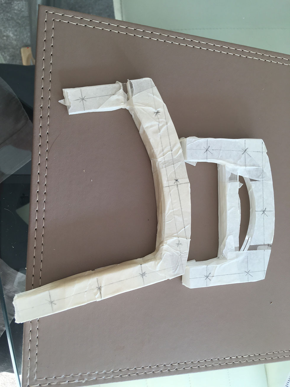
Next I drilled the holes in the acrylic parts ready for the sides o the suspension to come together so I could get an idea of what my robot looked like for the first time. As I experienced cracking and splitting in the process of drilling I decided to tape all around the parts of acrylic with masking tape so I would know where to drill and to keep the parts in place while I drilled through all three layers at the same time.
This method resulted in nice and clean cuts which ensured that all of the pieces would fit together nicely during assembly. I also had to be careful where placing the holes to make sure everything would line up as I want to reduce sanding and filing of parts as much as possible.
After cutting out the parts I had designed on the computer with the laser cutter and drilling the holes, the final stage of making the rockers and bogies for this robot's suspension was to assemble everything.

Now that everything was prepared, all I had to do was assemble it. Easy. Once I got hold of some nuts and bolts, I carefully assembled each part individually before attaching the two parts to make one side of the suspension. The connection between the rocker and bogie involves one single nylon-locking nut (so that it will not come loose when it rotates) , three washers between each layer (so it rotates freely) , the bolt and just enough tension so that the parts are secure but can also move and rotate freely.
The next step is to prepare the main chassis by drilling more holes and bolting the two bases together using spacers which I will hopefully have done by the next robot update. The thumbnail is just the base plate balanced on the rockers to give some idea of what the robot will look like. Here is another image below of when I began taping the body so I could figure out the spacing.

Thanks for reading! Please consider signing up to this blog (it's completely free) so that you can be the first to see any updates or posts.
Please Like, Subscribe and Leave a comment if you enjoyed this post!
![[01] Build a self-balancing robot with legs... (Boston dynamics Handle Inspired)](https://static.wixstatic.com/media/f57ec6_50671b7128e24948b992427d9e6484e4~mv2.jpg/v1/fill/w_980,h_935,al_c,q_85,usm_0.66_1.00_0.01,enc_avif,quality_auto/f57ec6_50671b7128e24948b992427d9e6484e4~mv2.jpg)

https://slatom.net/read-blog/12320https://prosafely.com/read-blog/25312
https://classix.bizlisting.cloud/dont-risk-it-buy-extended-warranty-for-electronics-from-warrantys-co-today/
https://webbiz.golocaly.online/dont-risk-it-buy-extended-warranty-for-electronics-from-warrantys-co-today/
https://articleshine.adseon.xyz/extend-the-life-of-your-devices-with-warrantys-cos-extended-warranty-plans/