![[02] How to build a self-balancing robot with legs! (Boston dynamics inspired) - It balances!](https://static.wixstatic.com/media/a27d24_4cc968a1028848819b1fc3eea2fa1e64~mv2.jpg/v1/fill/w_1019,h_576,fp_0.50_0.50,q_30,blur_30,enc_avif,quality_auto/a27d24_4cc968a1028848819b1fc3eea2fa1e64~mv2.jpg)
![[02] How to build a self-balancing robot with legs! (Boston dynamics inspired) - It balances!](https://static.wixstatic.com/media/a27d24_4cc968a1028848819b1fc3eea2fa1e64~mv2.jpg/v1/fill/w_1019,h_576,fp_0.50_0.50,q_90,enc_avif,quality_auto/a27d24_4cc968a1028848819b1fc3eea2fa1e64~mv2.jpg)
![[01] Build a self-balancing robot with legs... (Boston dynamics Handle Inspired)](https://static.wixstatic.com/media/f57ec6_50671b7128e24948b992427d9e6484e4~mv2.jpg/v1/fill/w_1776,h_1000,fp_0.50_0.50,q_30,blur_30,enc_avif,quality_auto/f57ec6_50671b7128e24948b992427d9e6484e4~mv2.jpg)
![[01] Build a self-balancing robot with legs... (Boston dynamics Handle Inspired)](https://static.wixstatic.com/media/f57ec6_50671b7128e24948b992427d9e6484e4~mv2.jpg/v1/fill/w_1172,h_660,fp_0.50_0.50,q_90,enc_avif,quality_auto/f57ec6_50671b7128e24948b992427d9e6484e4~mv2.jpg)
![[03] How to make a (Mini) Boston Dynamics Handle Robot - Balancing Robot using Arduino and Raspberry](https://i.ytimg.com/vi/4gV2Fx320o8/maxresdefault.jpg)
[02] How to build a self-balancing robot with legs! (Boston dynamics inspired) - It balances!
- raspibotics

- Jul 22, 2020
- 5 min read
Updated: Aug 13, 2020
(Update: GitHub repo now online https://github.com/raspibotics/MABEL)
Hello fellow roboteers! I've made quite a bit of progress since the last post, mainly on the Arduino/Hardware side of things, I'm still waiting to get it balancing and move the legs at the same time - A controller for the Pi is on its way now! The robot now balances very nicely using the handy YABR software package (If you haven't got that download it now as it will be a key resource to the build) that I'm using to base my project code off of. It also details how to setup the robot code and electronics properly, although I've made some simplifications/improvements. I've made a switch to A4988 Drivers and a CNC shield that sits on top of the Arduino to neaten up wiring. I've switched over the power system to LiPo batteries and designed a neat backpack to hold them on to the back of the bot where they can be removed easily and designed the next phase of the design in CAD. Remember you can download all of the 3D models for free from thingiverse. This blog post is not designed to be a step by step tutorial as most of the build is covered in the YABR build guide very nicely (and I'm still working on my robot), the main differences are in the addition of servos and a different shell design, which is relatively simple to construct with only a few nuts and bolts.
Sorting out the electronics (and releasing some magic smoke...)
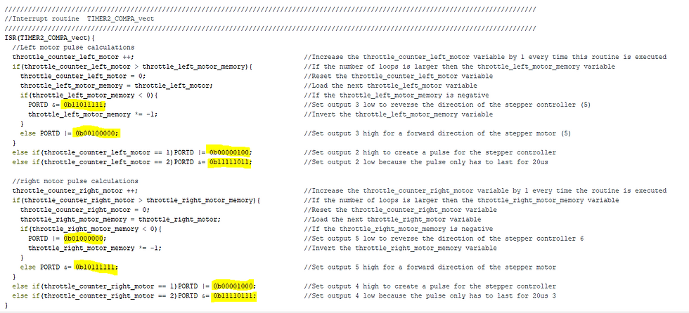
The first job following on from where I left off was to sort out the driver and power electronics. I decided to deviate from the YABR build and use the less expensive A4988 Stepper Motor Drivers as they were really cheap and came with a CNC shield that makes the wiring a lot easier and more modular. Having the drivers floating around (and having blown up a few) with a mess of cables was less than ideal, so I decided to use a handy CNC shield. It sits on top of my Arduino Uno and makes all of the connections from the drivers to the Arduino and battery in one compact PCB. The wires from the 5V regulator plug straight into the shield giving the arduino, driver logic and IMU (MPU-6050) power. The CNC shield breaks out the I2c bus so the IMU can be plugged right in using jumper cables. The connection from the battery also goes into the board to power the stepper motors as well as going to the 5V regulator (In parallel so both devices receive the full 11.1V of the LiPo battery). There are some important jumpers to place on the board in order to get it to work with the YABR software package: EN/GND must be bridged and the microstepping jumpers must be in the middle spot only. It's also really important that you place the Drivers in the right way around, lining the enable pins on the CNC Shield and the driver up.There are also some slight changes to the code to make to account for new pin mapping but I'll get to that later.


The Raspberry Pi Zero W, Servo Controller and IMU sit nicely underneath the arduino stack - I've created a quick timelapse of the Servo Wiring and Pi Installation below. The MPU-6050 is hot-glued (definitely not the best solution but it works) flat onto one of the Servos, it's important to mount the sensor in the correct orientation in relation to whatever you consider to be the front of the robot (which you should mark to keep track of). This is covered very well in the YABR project. The new bits of robot chassis I've published all fit on to the 3D Models linked in Part 1 with M5 Bolts to make sure that everything is secure, I've also modelled in some Wire Routing holes to better cable manage the wires from the LiPo battery into the robot.
Here are the updated Pin Numbers and port names I've figured out which you will need if you're following along and using the Arduino Uno and CNC Shield like me, these are the only changes that need to be made except changing the balancing value, which is covered in the YABR Setup process.

The Initial Balancing tests and beyond...
I was able to get the robot balancing even just using the Default PID Values in the YABR Arduino code but i think that they could be tuned a bit better, I'm pretty sure that my Derivative Value is too high which causes the robot to shake a bit, however I found that by adding a second body segment and Servos to move the head around (adding weight at the top of the robot) it made the bot naturally more stable. Speaking of the robot head, The pan/tilt mechanism is really simple to assemble and just requires two servos, 4 M4 bolts to mount it to the bot and an M3 bolt and servo horn - the parts should click into place. Adding the battery pack at the back of the robot also helps this, but it requires the servos to position the robot a bit further forward than normal to balance out. I'll be sure to update the PID values on the blog as I go along, so you don't have to go through the tedious process.

Here's the Current design in Fusion 360 (You can get the Fusion file on thingiverse if you need to make any changes to the design) - I've added Mounting holes on the sides for Arms, (I've not forgotten! Servos are expensive!) modelled a concept head design that could be populated with sensors and cameras and I've added holes to mount a HC-SR04 Ultrasonic Distance Sensor on the back of the robot so that the robot can take active precautions and not rely on the PID controller all of the time - this behaviour will be managed by the Pi that will overrule driving commands and take avoidance measures if the protective distance is exceeded, minimising falls and increasing stability.

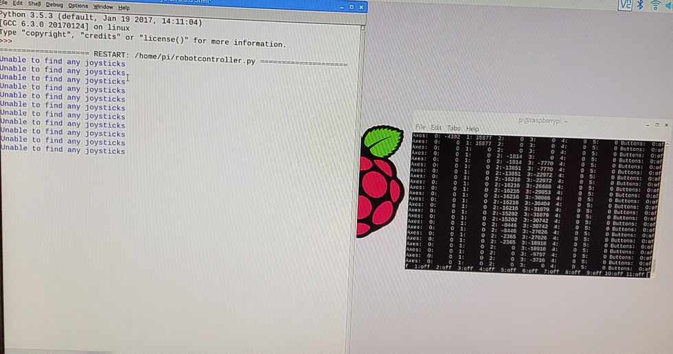
On the Pi side of things, I've got the first test scripts of Pi-Arduino Serial communication working. By my next post you will be able to send joystick data to the Pi from a Video Games controller using the fantastic Input python Library, convert that data to a Binary command that's compatible with the driving section of the code in the YABR firmware. If you've read part 1, you'll know that I've already succeeded in doing the Inverse Kinematics maths and controlling the servos using the Pi, I just need to tie everything together so I can publish the Pi code. I've tested whether the robot will turn and everything looks ok so I'm hoping that I get controls working shortly. I had limited success trying to get the PS3 controller to work, I think it was just a bit old and I was using a 3rd party one. I'm ordering a PiHut Controller that's specifically designed to work with the Pi, so it should be relatively quick for me to get it to work, the hard bit is done now!
Please hang in for Part 3 which will be the last post of my balancing robot adventure, where I get the robot driving around and make use of those legs (Jumping?)! I might do updates if I add arms or object recognition in the future but I want the basic legs build to span 3 parts. If you want to build my robot, that's great! Please don't hesitate to get in contact and I can help answer any questions. Thanks for reading!
![[01] Build a self-balancing robot with legs... (Boston dynamics Handle Inspired)](https://static.wixstatic.com/media/f57ec6_50671b7128e24948b992427d9e6484e4~mv2.jpg/v1/fill/w_980,h_935,al_c,q_85,usm_0.66_1.00_0.01,enc_avif,quality_auto/f57ec6_50671b7128e24948b992427d9e6484e4~mv2.jpg)

https://clik.social/read-blog/56060
https://blog.rackons.in/latest-lottery-news-and-updates-from-khelraja-india
https://thesn.eu/blogs/79171/Play-Lottery-India-with-Khelraja-for-Big-Jackpots
https://droidt99.com/read-blog/28875
https://www.asianfanfics.com/blog/view/1331764