![[02] How to build a self-balancing robot with legs! (Boston dynamics inspired) - It balances!](https://static.wixstatic.com/media/a27d24_4cc968a1028848819b1fc3eea2fa1e64~mv2.jpg/v1/fill/w_1019,h_576,fp_0.50_0.50,q_30,blur_30,enc_avif,quality_auto/a27d24_4cc968a1028848819b1fc3eea2fa1e64~mv2.jpg)
![[02] How to build a self-balancing robot with legs! (Boston dynamics inspired) - It balances!](https://static.wixstatic.com/media/a27d24_4cc968a1028848819b1fc3eea2fa1e64~mv2.jpg/v1/fill/w_1019,h_576,fp_0.50_0.50,q_90,enc_avif,quality_auto/a27d24_4cc968a1028848819b1fc3eea2fa1e64~mv2.jpg)
![[01] Build a self-balancing robot with legs... (Boston dynamics Handle Inspired)](https://static.wixstatic.com/media/f57ec6_50671b7128e24948b992427d9e6484e4~mv2.jpg/v1/fill/w_1776,h_1000,fp_0.50_0.50,q_30,blur_30,enc_avif,quality_auto/f57ec6_50671b7128e24948b992427d9e6484e4~mv2.jpg)
![[01] Build a self-balancing robot with legs... (Boston dynamics Handle Inspired)](https://static.wixstatic.com/media/f57ec6_50671b7128e24948b992427d9e6484e4~mv2.jpg/v1/fill/w_1172,h_660,fp_0.50_0.50,q_90,enc_avif,quality_auto/f57ec6_50671b7128e24948b992427d9e6484e4~mv2.jpg)
![[03] How to make a (Mini) Boston Dynamics Handle Robot - Balancing Robot using Arduino and Raspberry](https://i.ytimg.com/vi/4gV2Fx320o8/maxresdefault.jpg)
[01] Build a self-balancing robot with legs... (Boston dynamics Handle Inspired)
- raspibotics

- May 10, 2020
- 7 min read
Updated: Aug 13, 2020
(Update: GitHub repo now in full swing!) So its been a while but I'm back to present progress on my most ambitious robotics project to date. I've decided to build my own self-balancing robot (SB-1) based off of Boston Dynamics' Handle robot - a unique balancing bot with arms and legs that give it extra agility. After watching numerous videos of the robot on YouTube, I decided to design and build my own pi-flavoured version and open-source my findings on GitHub and Thingiverse after learning that my project is almost unique to the Pi World so that anyone with a 3D printer and a few bits can build one! (Part 2 is out now and the robot balances! Be sure to check it out after you're done reading this...
At the moment just the CAD and a section of code is available, when the robot progresses Updates will be posted following up with the extra relevant resources
Selecting the components
As a student, I'm on a tight budget so I've used off the shelf hobby components that can be bought off of Amazon for cheap. I really wanted to make my design unique as there are already loads of fixed balancing robot projects out there. The addition of servos to manipulate limbs on wheels brings a challenge with a number of benefits. Namely, being able to adjust the height of each leg to remain stable even when tipping from side to side and greater off-road capability as well as even jumping (may need faster servos though). For the wheel motors, 2x 38mm Depth NEMA 17 Stepper Motors are used as they are widely available for 3D Printing and have great precision, hopefully allowing for more stable balancing later on. To move the legs 2 MG996R metal gear servos are used for each leg. These servos can be bought for cheap (more expensive ones may be better suited however) and allow for precise control over their position which is handy when generating an Inverse Kinematics (IK) Handler to move the legs up and down straight later on. I'm also using an Arduino Uno to handle all of the PID calculations that will make the bot balance as it's better at real-time stuff than the pi.
Here's a complete parts list to date (subject to change): Go to Amazon basket.
3D Print all of the plastic parts (PLA or PETG) - Get the parts on my Thingiverse page for free. Print 4x Driver Gear, 1x Housing, 2x Lower Leg and Upper Leg sections, 2x body side panels, 1x Upper Body Housing, 1x battery pack, 1x Body Top and the Pan/tilt assembly to move the head.
Rubber 'O' rings or some grippy material to use for tyre treads.
2x 38mm NEMA 17 Stepper Motor
6x MG996R metal gear servos (2 are used for the head)
6x Aluminium servo horns (MG996R)
2x DRV8825 (or A4988) stepper Drivers
Arduino CNC shield
MPU6050 gyro/accelerometer
Arduino Uno (or micro)
Raspberry Pi
8x 10mm diameter Bearings (5mm internal diameter - 2 of these are used in each lower and Upper Leg Section)
12x 10mm M3 bolts (For stepper motors)
8x 15mm M5 bolts (For Body - More may be required when project progresses)
4x 25mm M5 bolts and locknuts (For Joints and Pivots)
16x 15mm M4 bolts (Attach servos to holders)
Some form of servo controller - I'm using a Piconzero HAT at the moment but I'll probably upgrade this in the future because it can only supply 5V to the servos, and I want to make it jump!
3S 3000mAh LiPo battery (and a LiPo charger)
2x Variable voltage regulator (one for servos, one for 5V devices like the Pi and Arduino
All of the parts cost about £125.00 assuming that you have a Raspberry Pi and Arduino. The cost is significantly less if you have screws to hand and a LiPo and charger.

The Mechanical assembly
Here's a pic of the current state of the robot, I'm just waiting on a few parts to come so I can get it balancing, but that will be detailed in a separate post. You might also wonder where the arms are but I've decided to get balancing working first before attempting to put some arms on. As you might notice (if you follow me on Twitter @raspibotics) this is V2; it has been redesigned from the original which was bulky and used springs to give the joints compliance and aid balancing by varying leg length to smooth out the ride over bumps and obstacles. Version 1 was based on James Bruton's prototype compliant joints that he's using for his MiniDog walking robot projects. After watching his video, I decided that this would be useful in my balancing robot. The only problem was that it made the thing huge. The problem the long length that acted as a force multiplier onto the servo shafts which they were bolted to. The servo shafts are not as secure as I would have liked and this led to significant wiggling and movement at the end of the leg. The springs only made things worse as the leg really needs to be rigid for balancing.
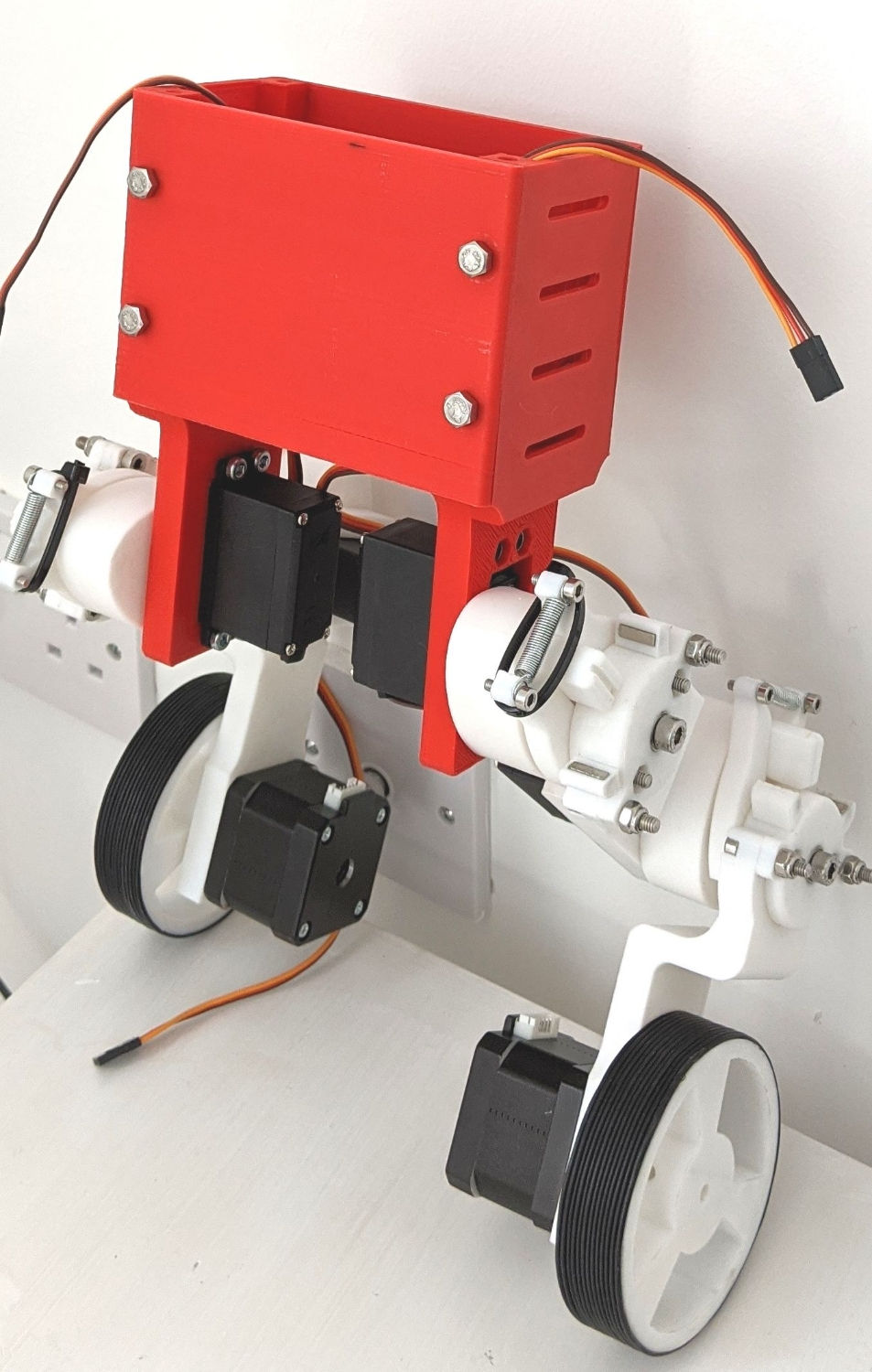
With this in mind, I got to work in Fusion 360 CAD to 3D model an improved version. Reducing the width of the joints, removing springs and adding a gear transmission to get rid of the load pushing on the servo,
eliminating leg wobble.
For each leg section (Upper leg or lower leg) 2x 10/5mm bearings are used with a M5 bolt and locknuts to secure the pivot to the other leg section, this is then driven by the driver gear that is attached to the Aluminium servo horn that pushes into the gear and onto the servo - secured by M3 bolts. This means that the load from the weight of the robot us supported by the two bearings and M5 bolt rather than the servo which only has a rotational load, making the robot more stable. However, now that the springs have been removed, another method is required to add a level of compliance and suspension so that the bot doesn't tip over when it hits the bump - I'll get to that later.

As you can see in the larger wheel part there is a hole in the top which accommodates a bearing and is the same on the bottom, allowing the leg to be properly supported. The larger wheel section requires two locknuts, one has to be put on backwards on the back of the wheel against the second bearing (a recess in the leg section allows it to sit flush) and the other goes on the other side of the leg to secure the entire thing. Note: the servos I received had a rib that meant they couldn't be mounted flat but this is really easy to file off. The servos are then secured in place with M4 bolts.


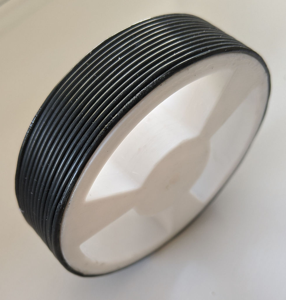
Another challenge was creating the right size wheels for the robot. I didn't have any of the right size available so I decided to 3D print my own wheels and use loads of little rubber o rings to create the tyre grip. The two outer rings are super glued in place to make sliding the rest of them on super easy. I experimented with other tyre materials earlier like old inner tube from a bike but nothing looked as clean or professional as the current wheel with the 'O' ring tyres that were suggested by my Dad. I also modelled in a hole for a M4 bolt to secure the wheel to the motor shaft in case friction isn't enough to keep the wheel from slipping.
Getting the legs moving (Inverse Kinematics test)
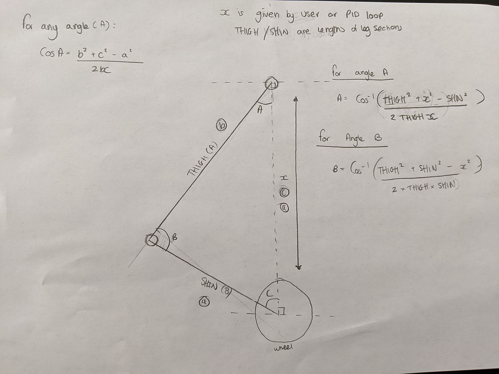
Moving legs up and down in a straight line might sound straightforward but there's more to it than you might think. Since the upper and lower leg sections are different lengths, they must be moved different angles for each position to maintain a straight position. Instead of manually figuring out angles for a limited number of positions we can create a function that takes an input of distance and automatically works out the angle required.
We can use the cosine rule to work out the angles in the triangle (which is effectively the problem) since we know the length of all sides (Two are constant; the lengths of the leg sections are measured, and the third length is given as X).
Once I had solved the equations on paper, I took to Python and got to work transferring it into code that could drive my servos. I'm using the PiconZero Library but this code should work for any servo controller that accepts angles as an input. The code works out each angle for the servo and then adds that value to the home position (this must be set as the legs facing directly downwards) so that the legs move in right angles to ground at all times. This ability is useful as it allows legs to be moved individually as well. In the future, i want to couple this kinematics code with a PID algorithm that varies the length of each leg according to the 'roll' rotational value from the gyroscope. This will keep the body level at all times, allowing for the PID controller keeping the whole balanced to be better suited to inclines and off-road navigation and decreasing the chance of tipping over. This means that the robot should have stability in all directions... Fingers crossed.
UPDATED: IK is solved for both X and Y axes, allowing full range of leg movement
When you input a distance, the script will figure out the angles required to make the distance between the pivot point of the upper leg to the centre of the wheel this distance.
This is the current state of the robot. The Inverse Kinematics code works and I am waiting on a few components to arrive before I can get it to balance (Battery and a new set of drivers - it's a long story) but i am confident that with my improved mechanical design it should be possible.
Next time... Electronics and PID Controllers and Balancing??
In the meantime, i encourage you to get all of the parts required printed off and order all of the parts. Maybe you can even beat me to get it balancing! I will start a GitHub Repository with all of the code once there is more to show but I just wanted to update everyone what I've been up to and start the long process of writing everything down.


Excellent insight, incorporating sex toys can deepen physical connection and intimacy.
I'm keen on building this. What's the story with the two arduino codes? Is the Balancing_robot.ino a modification of the yarba test code?